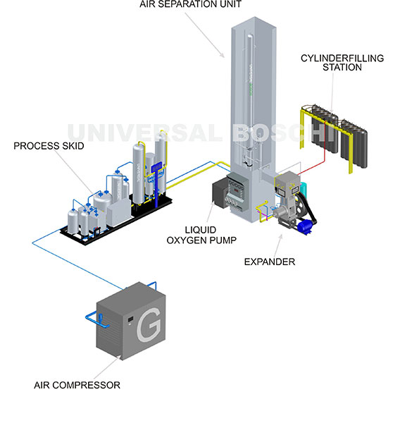
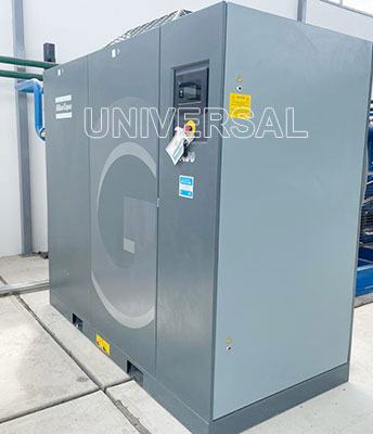
The atmospheric air is sucked in by a multi-stage air compressor through a filter and compressed to the working pressure. After each stage, inter coolers and water moisture separators are provided. The air then passes through the (evaporation) CASCADE BUBBLER and then to the chilling unit before entering the molecular sieve battery where the moisture and carbon dioxide are removed from the process air. It then passes through the exchanger No. 1 where it is cooled by the waste nitrogen and product oxygen which are coming out.
One part of this cold air then flows through an expansion engine and the balance through the heat exchanger. No. 2 The balance of the ratio of the two air streams is controlled by an expansion valve, all the two streams of air then combine in the lower column where it liquefies partly.
The liquid air which is crude liquid (rich air) goes through the expansion valve no. 2 to the upper column which is at a lower pressure of about 0.5 bar than the lower column about 5 bar. Similarly the liquid nitrogen (called pl or poor liquid) is throttled as reflux via a sub cooler from the lower column to the upper column through an expansion valve no, 3 where the air is separated into oxygen and nitrogen. Nitrogen being more light and having a lower boiling point passes out as a gas from the top of the upper column and this nitrogen flows through both the heat exchangers no. 1 and heat exchanger no 2 where the liquid oxygen is vaporised by giving the cooling the in-coming air. Similarly pure oxygen at 99.6% purity which is achieved in the upper column is also passed through the two heat exchangers to cool the in-coming air and then to the filling manifold via a liquid oxygen pump.
If a small amount of air is vented out from the upper column, higher purity nitrogen can also be obtained from this plant. Valve no. 4 which is called the by pass valve after the air coming out of the expansion engine.
Range: 20 m3/hr to 1000 m3/hr
With leakproof stainless steel column and skid mounted version for high purity medical and industrial oxygen.

|
Technical Specifications
|
|||||||||||
| Name of the Models | UB - 20 | UB - 30 | UB - 50 | UB - 80 | UB - 100 | UB - 150 | UB - 200 | UB - 300 | UB - 400 | UB - 500 | UB - 1000 |
| Capacities (Cubicmeter/hr) | 20 | 30 | 50 | 80 | 100 | 150 | 200 | 300 | 400 | 500 | 1000 |
| No. of Cylinders
in a Day (Oxygen/Nitrogen) |
80 | 100 | 200 | 300 | 400 | 600 | 800 | 1200 | 1600 | 2000 | 4000 |
*Filling of oxygen by liquid oxygen pumps, liquid nitrogen pump is optional.
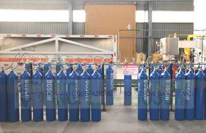
UB series oxygen/nitrogen plants are used for filling high pressure Oxygen/nitrogen gas in cylinders/bottles by liquid oxygen pump (oil free & water free) for industrial & medical applications. For filling liquid oxygen & liquid nitrogen additional liquid tapping facility is available.
Step 1: Compression of Atmospheric Air
Step 2: Purification of Air: COMPACT PROCESS SKID
Step 3: Cooling of Air
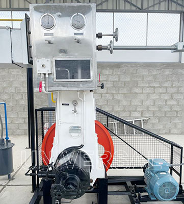
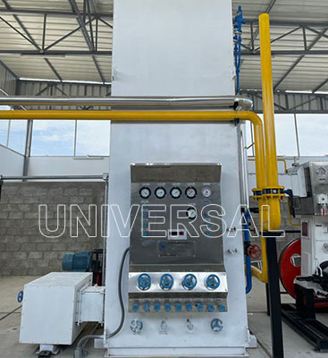
LATEST LEAKPROOF STAINLESS STEEL COLUMN
Compression/Withdrawl and Filling of Oxygen and Nitrogen by latest liquid oxygen pump technology to fill bone dry high purity oxygen in Cylinders. Now, no need of old type of bulky oxygen compressors, no more break downs, moisture or rusting in cylinders. Thanks to the latest liquid oxygen pump technology
This is a multistage air compressor complete with flywheel inter cooler, motor pulley, motor, v-belts, guard and slide rails and air skid mounted versions to avoid civil for quick installation. This is used to compress foundation bolt, filter. This can also be supplied in foundation atomspheric air.
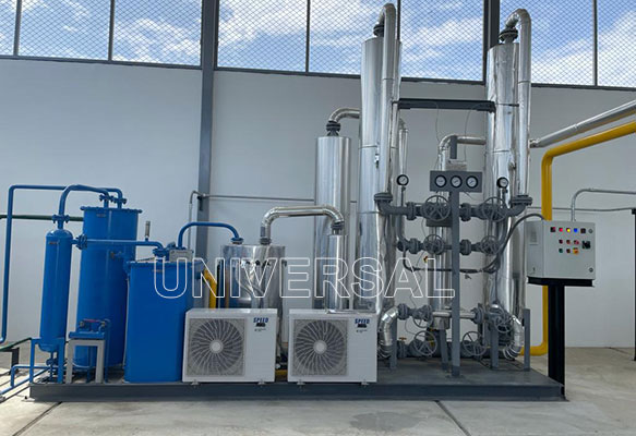
This consists of purification of the air by removing moisture, oil traces and carbon di oxide in the process air. Compressed air is chilled to 12°C in a chilling unit and evaporation cooler, compressed air passes through the oils of the hilling unit at a temperature of 12°C to a moisture separator, where the condensed moisture gets removed before entering into Molecular Sieve Battery. Before sending the air to MOLECULAR SIEVE BATTERY, air is passed through an OIL ABSORBER where air becomes oil free. Chilled air passes through the Molecular Sieve Battery consisting of Twin Tower packed with molecular sieves to remove moisture and carbon dioxide present in the air.
The process air before liquefication in the air separation unit needs to be cooled to temperatures sub-zero (cryogenic). The main portion of the air after the process skid enters the expansion engine through the heat exchanger no.1 after pre-cooling. The temperature of the air drops to around -165 deg Celsius by the Expander which is a very highly efficient advanced design with Teflon piston rings and completely hydraulic mechanism with leakproof ball valves.
Rest of air at (-80) degC from Heat Exchanger No.1 enters into a highly efficient EXPANSION ENGINE, where the air further gets cooled down to (-150)deg Celsius before entering into bottom column. The liquefied air from both these streams collected at the BOTTOM COLUMN is known as RICH LIQUID.
After the process skid, the air enters the air separation unit (cold box)where the air converts into liquid air by deep cooling at cryogenic (low temperatures)and is separated into liquid oxygen and nitrogen. Chilled, Oil-free and moisture-free air enters into multi-pass HEAT EXCHANGER No.1 where it gets cooled to (-80)deg Celsius by cold gained from outgoing waste nitrogen and oxygen. A part of air, this enters a multi-pass HEAT EXCHANGER NO.II or LIQUEFIER made of special alloy tubes. This air cools to (-170)deg Celsius before passing through an expansion valve. Due to Joule Thompson Effect after the expansion valve, air gets further cooled down and gets liquefied before entering into Bottom Column.
After the process skid, the air enters the air separation unit (cold box)where the air converts into liquid air by deep cooling at cryogenic (low temperatures)and is separated into liquid oxygen and nitrogen. Chilled, Oil-free and moisture-free air enters into multi-pass HEAT EXCHANGER No.1 where it gets cooled to (-80)deg Celsius by cold gained from outgoing waste nitrogen and oxygen. A part of air, this enters a multi-pass HEAT EXCHANGER NO.II or LIQUEFIER made of special alloy tubes. This air cools to (-170)deg Celsius before passing through an expansion valve. Due to Joule Thompson Effect after the expansion valve, air gets further cooled down and gets liquefied before entering into Bottom Column.